Application of LB series servo motor and KAD double axis driver in six axis welding manipulator
1. System Description
Manipulator is a kind of automatic equipment. The arm is the basic part of the robot manipulator, which can rotation and reciprocating motion. It is mainly used in machining, casting and forging, heat treatment and spot welding. The welding manipulator is mainly used for spot welding. A fixed welding gun is installed at the end of the welding manipulator, which can realize the function of automatic welding. The servo system of welding manipulator is mainly used to control the machine wall. The corresponding action control of servo driver is completed by torque control
Servo requirements of welding manipulator
The system is composed of six sets of servo drivers and servo motors, and the field figure is as follows

Introduction to industry matching performance
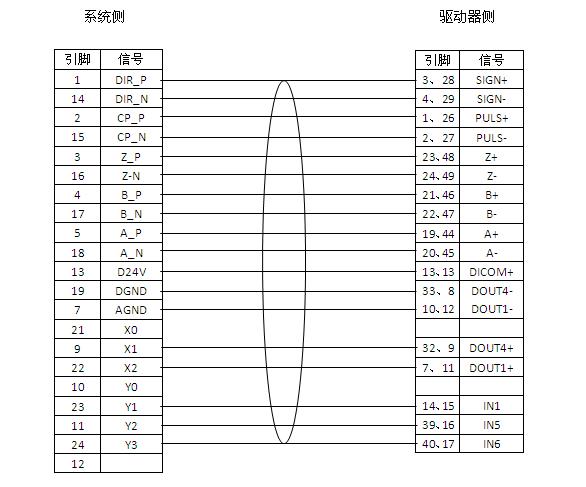
The host computer is connected with the control end of the servo driver, and the control mode is torque control. The wiring between the host computer and the system is as follows:
Application and debugging of LB series servo motor and KAD double axis driver in six axis welding manipulator
1 Servo drive and motor configuration
| Device name | Six joint welding robot | |
| Drive and motor configuration | Drive model | Motor type |
| X axis |
ZSD-KAD20AA |
110ST-M05030LFB/Z |
| Y axis | 110ST-M05030LFB/Z | |
| Z axis | 80ST-M02430LF1B | |
| A axis | 80ST-M00630LF1B | |
| B axis | 80ST-M00630LF1B | |
| C axis | 80ST-M00630LF1B | |
2 Related parameter settings
⑴Velocity loop proportional gain
When the gain value is increased, the speed responsiveness can be improved, so that the driver can drive the motor as timely and accurately as possible according to the command. However, if the setting is too large, it is easy to generate vibration and noise. Therefore, the appropriate value should be selected according to the actual situation
⑵Position loop gain
Increase the gain of the position loop to accelerate the system response. Reduce positioning error and shorten positioning time. However, mechanical vibration and system position overshoot are caused by excessive meeting
⑶Electronic gear ratio setting
Reciprocal of ratio of target value to actual value
⑶Position command acceleration / deceleration time parameter
⑷Brake command – servo off delay time
⑸Torque command filter time parameter
⑹RS-485 RS-485 communication parameter selection switch
⑺RS-485 RS-485 communication axis address
Post time: Mar-04-2020