1.Introduction
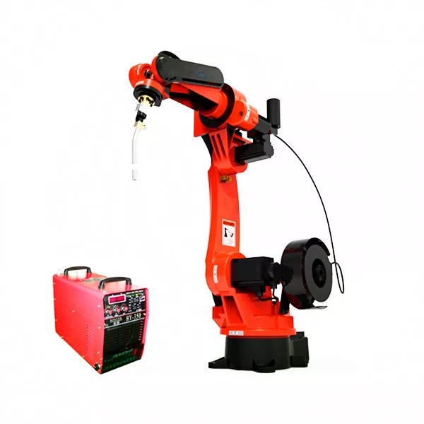
With the improvement of automation level of industrial production line, it tends to be flexible development.Industrial manipulator is more and more used in painting, packaging, welding, assembly and other production processing to Instead of the artificial to complete the work in the severe environment.In this paper, the six axis hot-dip galvanized manipulator is taken as an example. In mechanism, the six axis manipulator is designed as a 6-DOF spatial coordinate system.All six shafts are operated by servo motor with reducer. The control system of carnop robot is used to control the servo driver to complete the corresponding action.
2.System introduction
1 Features of six axis industrial manipulator:
(1) High speed: light components and high-power micro motor are used to improve the speed, thus shortening the cycle time and improving the production efficiency.
(2) High precision: the six axis industrial manipulator adopts high-quality and high-performance harmonic reducer, which makes the repeated positioning in the operation engineering and ensures the precision.
(3) Good sealing performance: the shaft is completely sealed, suitable for use in the harsh environment with high requirements for the sealing performance of dust, oil, harmful gas liquid, etc.
(4)Small size and large load
2 Advantages of six axis industrial manipulator
(1).Six axis industrial manipulator response time period, rapid action, fast speed, robot in the process of operation without pause, no rest, improve the efficiency of automatic production.
(2).The six axis industrial manipulator has high precision and little influence on the quality, so the product quality can be guaranteed.
(3).Using six axis industrial robot can reduce labor cost and material waste.
(4).It can adapt to the production of different artifact by modifying the program, shorten the period of product transformation and the investment of application equipment.
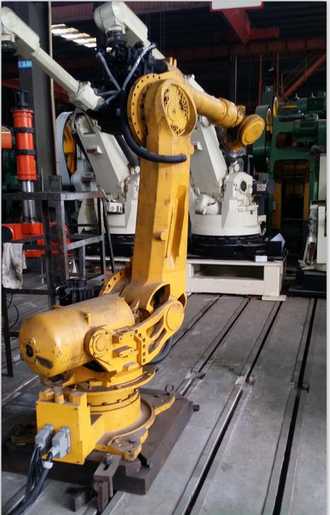
(5).Instead of manual work, work in high-risk, harmful and other harsh environment.
3. Servo requirements of six axis manipulator
The six axis galvanized manipulator is mainly composed of six sets of servo drivers and motors matched with reducer to complete the positioning and rotation of the manipulator. In addition, two sets of servo drivers and motors are responsible for feeding. Among them, axis 1, 2 and 3 are composed of ZSD-KBS50AB with 180ST-M27020HM1BB motor, axis 4, 5 and 6 are composed of ZSD-KAS20AB with 130ST-M10015LM1BB motor. 7. 8-axis is composed of ZSD-KAS20AB and 110ST-M06030LM1BB motor. All servo drivers work in position mode. Robot control system sends control signals to servo drivers and drives servo motors to complete corresponding actions. Shown as below :
4.Introduction to industry matching performance
The host computer is connected with the control terminal of the servo driver. The control mode is pulse + direction in the position mode. The host computer sends the position command to the servo driver. The servo driver drives the motor to complete the corresponding action according to the command. The control terminal wiring is defined as follows:
5.Application of IK servo drive and LMBB servo motor in six axis manipulator
1 Servo drive and motor configuration
|
Axis |
AC Servo driver model |
Ac Servo motor model |
|
1# |
KBS50AB |
180ST-M27020LM1BB |
|
2# |
KBS50AB |
180ST-M27020LM1BB |
|
3# |
KBS50AB |
180ST-M27020LM1BB |
|
4# |
KAS20AB |
130ST-M10015LM1BB |
|
5# |
KAS20AB |
130ST-M10015LM1BB |
|
6# |
KAS20AB |
130ST-M10015LM1BB |
|
7#(Feeding) |
KAS20AB |
13ST-M06030LM1BB |
|
8#(Feeding) |
KAS20AB |
13ST-M06030LM1BB |
2 Related parameter settings
(1)Electronic gear ratio
Control resolution according to specific application requirements
(2)Velocity loop integral time constant
When this parameter is reduced, the speed responsiveness can be improved and the speed control error can be reduced. However, if the setting is too small, it is easy to generate vibration and noise, the greater the parameter, the worse the rigidity.
(3)Velocity loop proportional gain
When the gain value is increased, the speed responsiveness can be improved. But if the setting is too large, it is easy to produce vibration and noise.
(4)Position loop gain
Increase the gain of the position loop to accelerate the system response. Reduce positioning error and shorten positioning time. However, mechanical vibration and system position overshoot are caused by excessive meeting
(5)Moment of inertia ratio
Ratio of load inertia and motor out of shaft inertia
(6)During fast start stop positioning, it is easy to generate low-frequency jitter at the end of the mechanical arm, which extend the positioning time and affects the production efficiency. The servo has built-in buffeting control function. The low-frequency jitter suppression function is enabled through PA004 parameter. The jitter frequency and damping are set through PA413 and PA414.
Post time: Mar-04-2020