1. System description
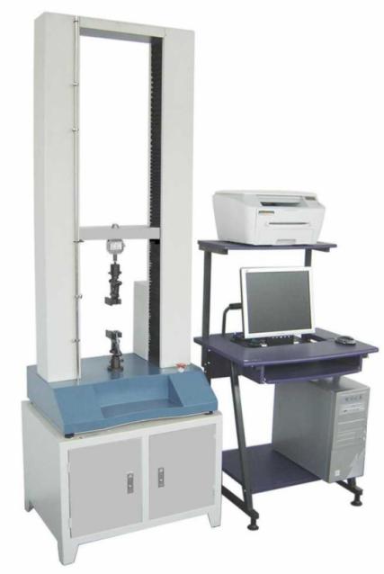
Electronic tensile testing machine is mainly used for tensile compression and bending test of plastic plate, pipe, profile, plastic film and rubber, wire and cable, waterproof roll, metal wire and other materials. It is an ideal testing equipment for industry and mining, commodity inspection and arbitration, scientific research units, colleges and universities, engineering quality monitoring stations and other parts. It is a kind of experimental instrument. With the rapid development of high technology, many old products have been gradually replaced by new and higher-level products. In the field of test instruments, most of the previous models using stepping motor have been replaced by servo system with better cost performance, especially the electronic tensile machine. Among them, the pulling force drive part adopts the AC servo motor plus reducer and the synchronous belt to drive the pulling arm up and down.
2.Servo requirements of electronic tensile testing machine
The system has high control requirements for the motor. In normal operation, the motor is required to run at a very low speed, and the balance of the motor torque is required to be maintained. When the work is completed, the motor will return to the origin with high speed. The actual displacement of the tension arm is calculated by the number of pulses output by the servo encoder, and the single pulse count is used for the upper count. As following:
Introduction to industry matching performance
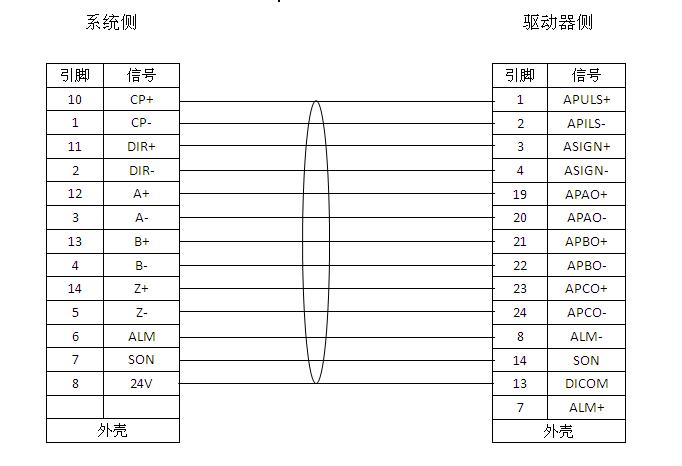
The host computer is connected with the control end of the servo driver, and the control mode is pulse + direction in the position mode. The wiring diagram is as follows:
Application and debugging of Huada servo motor LB series and K series servo drivers in electronic tensile testing machine
1、Related parameter settings
⑴Velocity loop proportional gain
When the gain value is increased, the speed responsiveness can be improved, so that the driver can drive the motor as timely and accurately as possible according to the command. However, if the setting is too large, it is easy to generate vibration and noise. Therefore, the appropriate value should be selected according to the actual situation.
⑵ Position loop gain
Increase the gain of the position loop to accelerate the system response. Reduce positioning error and shorten positioning time. However, mechanical vibration and system position overshoot are caused by excessive meeting.
⑶Electronic gear ratio setting
Reciprocal of target value to the actual value ratio
⑷Position command acceleration / deceleration time parameter
Post time: Mar-04-2020